


Views: 0 Author: Site Editor Publish Time: 2026-10-16 Origin: Site


Replacing a failed hydraulic pump is rarely a simple swap. Relying solely on a faded nameplate or a legacy part number introduces significant operational risk. You face severe consequences when you install mismatched components. Installing an incompatible pump results in immediate cavitation, blown seals, or catastrophic system failure upon startup. These rapid failures destroy expensive internal components and cause massive fluid leaks.
This guide provides a definitive engineering and procurement framework to verify exact compatibility. We ensure your replacement pump integrates seamlessly into your existing hydraulic circuit. You will learn how to measure physical dimensions accurately. We will teach you how to validate critical fluid power specifications. Finally, you will understand how to evaluate advanced control systems before you make a purchase.
Many technicians assume a matching part number guarantees a perfect replacement. This assumption often leads to costly mistakes. Original Equipment Manufacturers (OEMs) frequently update their part numbers over time. They alter casting molds to improve manufacturing efficiency. They also switch sub-tier suppliers to reduce production costs. These background changes mean a matching part number today might not share identical physical dimensions with a decade-old unit. You might discover shifted bolt patterns or slightly wider housings during installation.
Heavy machinery manufacturers also create a significant blind spot. Equipment builders frequently request proprietary modifications from pump manufacturers. They might ask for specific control valve settings. They often specify unique splines to match proprietary gearboxes. However, the manufacturer usually sells these modified units under standard pump model codes. If you purchase an off-the-shelf unit sharing the same base code, it will likely fail to interface correctly. Proper hydraulic pump compatibility analysis prevents this exact scenario.
You must establish a strict verification rule. If the original pump lacks a legible data plate, cross-verification is non-negotiable. You cannot guess the specifications. You must manually measure all physical parameters. You must calculate the fluid power requirements based on system schematics. Do not authorize a purchase order until you cross-reference every dimensional and performance metric.
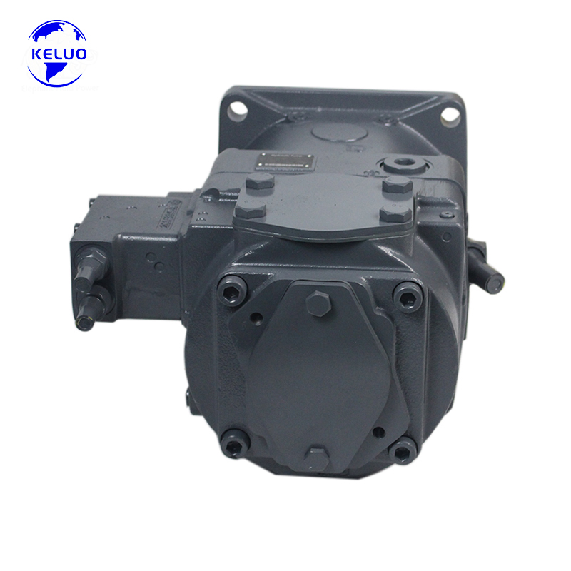
Physical compatibility determines whether the new pump will physically bolt onto your machine. A minor dimensional error stops an installation completely.
You must compare standard SAE configurations (such as A, B, C, or D) against ISO mounting standards. These standards dictate the overall shape and mounting interface. Detail the importance of verifying the pilot diameter first. The pilot ring must seat perfectly into the housing to ensure shaft alignment. Next, measure the bolt hole spacing using digital calipers. A single millimeter of deviation prevents proper seating. Forced seating will crack the mounting flange.
Common SAE Flange Measurement Guide
| SAE Flange Size | Pilot Diameter (Inches) | Bolt Hole Spacing (Inches) | Number of Bolts |
|---|---|---|---|
| SAE A | 3.250 | 4.187 | 2 |
| SAE B | 4.000 | 5.750 | 2 or 4 |
| SAE C | 5.000 | 6.375 | 2 or 4 |
Drive shafts transfer mechanical energy into fluid power. You must contrast keyed shafts, splined shafts, and tapered shafts carefully. Keyed shafts use a single rectangular key to lock the coupling. Splined shafts use multiple teeth for high-torque applications. Tapered shafts lock into a matching conical hub. Writer Note: Highlight that a minor mismatch in spline count or shaft length will destroy the coupling. It will also shear the shaft completely under heavy load. Count the splines twice. Measure the shaft extension length precisely.
Inlet and outlet ports connect the pump to your hydraulic circuit. You must verify these port types meticulously. Common options include:
You must also assess port orientation. Compare rear-ported designs against side-ported designs. The replacement pump must fit within the machine's physical envelope. A rear-ported pump might hit the engine block if a side-ported pump originally occupied the space. This error requires costly, time-consuming hose rerouting. It often introduces unnecessary bends into the plumbing.
Performance matching ensures the new unit generates the correct flow and pressure. It guarantees your actuators move at the desired speed and force.
You must match the cubic inches or centimeters per revolution (CID/cc). This metric defines volumetric displacement. Displacement dictates how much fluid moves during one complete shaft rotation. Oversizing the pump causes severe heat generation. It forces excess fluid over the relief valve, creating a system bottleneck. Conversely, undersizing the pump leads to sluggish actuator response. Your hydraulic cylinders will move slowly, reducing overall machine productivity.
Hydraulic systems experience dynamic pressure loads. You must clarify the difference between operating pressure and intermittent peak pressure. Continuous operating pressure is the normal load during standard operation. Peak pressure represents brief pressure spikes during heavy sudden loads. Ensure the replacement pump is rated for the system’s primary relief valve setting. If the relief valve is set at 4,000 PSI, the pump must handle 4,000 PSI continuously. Installing a 3,000 PSI pump here guarantees premature failure.
Rotation direction dictates fluid flow paths. We provide a hard rule here. You must verify Clockwise (CW) versus Counter-Clockwise (CCW) rotation directly from the shaft end. Stand facing the input shaft to determine the correct orientation. Risk Warning: Running a unidirectional pump backward will instantly destroy internal components. It creates a vacuum on the pressure side and forces high-pressure fluid into the suction seals. To avoid this, utilize a rigorous hydraulic pump compatibility checklist before installation.
Modern hydraulic systems rely on intricate control logic. The pump must communicate correctly with the larger circuit architecture.
Ensure the internal valving matches the circuit architecture perfectly. Open-loop systems draw fluid from a reservoir and pump it to directional valves. Closed-loop systems recirculate fluid directly back from the hydraulic motor to the pump inlet. You cannot interchange open-loop and closed-loop pumps. Their internal porting and charge pump configurations differ drastically.
Variable displacement pumps use complex control mechanisms. You must evaluate the compatibility of pressure compensators. You must also check load-sensing (LS) controls and proportional electronic displacement controls. Assess whether the existing control blocks can be transferred easily to the new pump. Some control blocks require complete recalibration upon transfer. An unmatched load-sensing control will cause the pump to stay at maximum stroke, wasting immense horsepower.
Internal seals interact directly with hydraulic fluid. Briefly confirm seal material compatibility. Standard Buna-N seals work perfectly well with mineral-based AW46 fluids. However, fire-resistant fluids, such as phosphate esters, instantly degrade Buna-N. These synthetic fluids require Viton seals. Check your reservoir fluid type. Ensure the new pump matches this viscosity and chemical profile.
Abstract concepts require practical examples. We use the Rexroth A11VLO190 plunger pump as a high-stakes, real-world evaluation example. Engineers frequently install this specific unit in heavy concrete pump trucks and massive tunnel boring machines. A failure in these applications stops entire construction sites.
You must check three critical areas when dealing with this specific variable piston pump.
Verify maximum displacement settings precisely. The A11VLO190 pushes 190cc per revolution. You must ensure the variable displacement controls (such as LR, DR, or EP controls) perfectly match the machine’s Engine Control Unit (ECU) parameters. If the ECU sends a specific milliamp signal, the proportional control must translate it accurately to adjust the swashplate angle. A mismatch disables variable flow capabilities.
Check if the original A11VLO190 drives a secondary tandem pump. Many mobile machines stack a gear pump behind the main piston pump. If it does, the replacement must have the exact matching rear-flange configuration. You must also verify the internal coupling type required to engage the secondary shaft.
Confirm whether the specific system application requires an integrated charge pump. High-speed operations draw massive amounts of fluid rapidly. This creates a vacuum at the inlet. The impeller version forces fluid into the main rotating group. It prevents high-velocity cavitation during maximum RPM cycles.
Deciding between rebuilding an old unit and purchasing a new replacement requires objective analysis. You must evaluate immediate financial outlays against long-term operational stability.
Verifying hydraulic pump compatibility is a strict, multi-dimensional process. It requires evaluating physical fit, measuring hydraulic output, and matching complex control logic. Skipping any of these steps results in catastrophic equipment failure and extended downtime. OEM part numbers only provide a starting baseline. You must cross-reference flanges, displacement, pressure ratings, and internal sealing materials to ensure success.
Take immediate action before purchasing your next unit. Document your system’s baseline metrics clearly. Measure the physical constraints of the mounting area. Always consult with a certified fluid power specialist before issuing the final purchase order. Expert review catches minor discrepancies before they become expensive problems.
Submit your current pump's nameplate data, system schematic, or specific failure symptoms to our engineering team today. We provide a definitive compatibility cross-reference and a comprehensive quote to keep your machinery running smoothly.
A: Look at the inlet and outlet port sizes. The inlet port is typically larger to prevent cavitation. Viewing the pump directly from the shaft end, if the inlet is on the right side and the outlet is on the left, it is generally clockwise (CW). Always consult a fluid power technician to confirm rotation based on internal porting.
A: Yes, you can. You must ensure the aftermarket unit meets or strictly exceeds the OEM's volumetric efficiency, maximum pressure ratings, and dimensional tolerances. Rigorous cross-referencing is absolutely required to guarantee successful integration.
A: Perform a case drain flow test for piston pumps, or use an inline flow meter under load. If fluid flow drops significantly as system pressure increases, internal component wear is critical. Advise against dangerous "deadhead" testing without proper relief valves.
A: The system will experience faster actuator speeds immediately. However, it will require more horsepower from the prime mover. This mismatch potentially causes engine stalling. It also generates excessive heat if the cooling circuit cannot handle the increased flow rate.


