


Views: 0 Author: Site Editor Publish Time: 2026-09-23 Origin: Site


Heavy machinery operators often face hidden operational costs caused by mismatched hydraulics. You might notice increased cycle times on the job site. You could see excessive fuel burn during routine digging operations. These symptoms frequently lead to premature component failure. These issues point directly to an imbalance between engine output and actual hydraulic demand. Resolving this requires immediate attention.
Selecting a replacement or upgrade pump requires more effort than matching baseline factory part numbers. You must understand the specific relationship between engine RPM, hydraulic flow, and actual working load. Sizing components blindly based on physical dimensions invites disaster. You need a rigorous mathematical approach to match fluid power generation with your machine's capabilities.
This guide provides the exact engineering foundation needed to make informed hydraulic upgrades. We will cover the mathematical framework required for sizing fluid power systems. You will learn how dynamic load considerations impact your final component choice. We also outline specific risk mitigation strategies for specifying hydraulic pump displacement. This knowledge ensures your excavator performs efficiently under the most demanding field conditions.
Displacement dictates the exact volume of fluid moved per rotation. We measure this metric in cubic centimeters per revolution (cc/rev). This figure strictly determines the speed of your hydraulic cylinders and motors. System pressure determines the brute force applied to the load. Understanding this distinction helps engineers size fluid power components accurately.
The matching formula bridges mechanical theory and physical reality. You calculate the necessary unit size using a highly dependable equation. The formula is: Required Displacement = (Desired Flow Rate × 1000) / (Engine RPM × Volumetric Efficiency). You plug in your known prime mover speeds. You then enter your desired gallons per minute (GPM) or liters per minute (LPM).
However, practical efficiency matters deeply in these calculations. Avoid assuming a theoretical 100 percent efficiency rate. Internal fluid slippage happens naturally in every hydraulic system. You should factor in an 85 to 95 percent volumetric efficiency rate. This accounts for internal design constraints. It also factors in fluid viscosity changes at extreme operating temperatures. Overlooking this detail leaves you with a sluggish machine response.
You must balance hydraulic pump displacement against the maximum allowable system pressure. If you ignore this metric, you risk exceeding the available horsepower of your diesel engine. The core horsepower formula is HP = (GPM × PSI) / 1714. This math prevents catastrophic engine stalling.
| Application Focus | Displacement Target | Operating Pressure | Engine Horsepower Demand | Primary Result |
|---|---|---|---|---|
| High Speed Trenching | High (Large cc/rev) | Low to Moderate (2000-2500 PSI) | High (Due to Flow) | Fast cylinder speeds, lower breakout force |
| Heavy Rock Breaking | Moderate (Medium cc/rev) | Very High (3500-5000 PSI) | High (Due to Pressure) | Massive breakout force, slower cycle times |
| Balanced General Use | Variable (Load Sensing) | Variable (Up to 4000 PSI) | Optimized / Dynamic | Excellent fuel efficiency, stable operation |
Operating a standard earthmoving bucket involves highly predictable load cycles. Operators swing, dig, lift, and dump in a smooth rhythm. The base factory displacement easily handles these repetitive mechanical actions. The engine RPM remains relatively stable throughout the cycle. Heavy auxiliary attachments completely disrupt this baseline operational pattern.
When you install tools like hydraulic breakers or shears, you alter the machine's peak demand. These complex attachments require sustained, specific fluid flow rates. High-frequency demolition tools draw massive amounts of hydraulic oil instantly.
If the calculated displacement falls short, the primary tool starves the rest of the hydraulic circuits. This starvation causes dangerous drops in operational control. You might experience a complete loss of swing function mid-lift.
Multi-circuit synchronization prevents catastrophic performance degradation on the job site. You must match the primary displacement perfectly with the internal priority valve system. When you activate auxiliary lines, your travel, swing, and boom functions should remain stable.
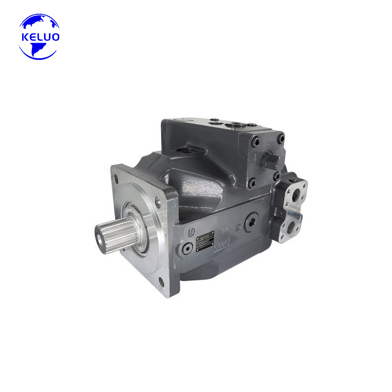
High-demand, continuous-duty excavator circuits require highly specialized internal components. Engineers typically categorize closed-loop, variable displacement axial piston pumps as the gold standard for these demanding setups. They adapt to fluctuating loads instantly and efficiently. You evaluate these advanced pumps through several specific performance lenses.
The Rexroth A4VSG500 hydraulic pump excels in complex industrial applications. We can analyze its performance across several strict operational criteria. These metrics prove its value in high-stress environments.
Ideal use cases for this tier of pump include massive machine weight classes. We also see them frequently in specific industrial pressing applications. Upgrading makes economic and mechanical sense here. Machines running demanding attachments constantly require this level of engineering.
Standard open-loop gear pumps simply cannot survive these operating conditions. They generate too much heat and waste valuable engine horsepower. Implementing a variable piston solution solves these thermal and mechanical bottlenecks permanently.
Many machine operators believe a larger displacement pump automatically yields better performance. This assumption acts as a dangerous industry myth. Upsizing without calculating true engine capacity creates severe mechanical consequences. You cannot force a small diesel engine to push a massive hydraulic load.
Excessive displacement causes immense parasitic horsepower loss. The engine quickly bogs down or stalls under heavy digging loads. Pushing too much fluid through standard hose lines elevates fluid velocities drastically. High fluid velocities lead to severe cavitation inside the directional control valves. You also generate excessive friction heat, often forcing you to install expensive aftermarket fluid coolers.
Conversely, under-sizing brings its own frustrating operational symptoms. You will notice incredibly slow cylinder actuator speeds. Trenching cycle times extend significantly, which ruins your daily project margins. A small pump cannot move enough fluid to keep the machine agile.
Most noticeably, operators lose the ability to perform multiple machine functions simultaneously. You cannot lift the boom, roll the bucket, and swing the cab at the same time. The fluid volume simply does not exist in the circuit. Precision matching prevents both of these extreme scenarios.
Proper sizing requires a careful review of your machine's original factory specifications. You must find the exact sweet spot between engine torque and fluid output. This balance ensures smooth operation, lower fuel consumption, and extended component lifespans.
A smooth upgrade requires precise technical communication with your parts vendor. Procurement engineers must supply exact system metrics before ordering a replacement. Guesswork leads to costly job site downtime and expensive return shipping fees. You need accurate data to secure the right component.
First, gather the essential baseline data points. You must identify the Engine Max RPM. Find the continuous operating PSI rating of the machine. Determine the required GPM for your highest-demand hydraulic attachment. Specify the exact fluid type currently residing in the main reservoir.
Next, verify the physical mounting and internal drive constraints. Buyers often forget to check the specific shaft type. Determine whether you need a splined shaft or a keyed shaft. Confirm the mounting flange adheres strictly to your required SAE or ISO physical standards. Always double-check the rotation direction, noting if the pump spins clockwise (CW) or counter-clockwise (CCW).
Finally, address crucial compliance and warranty considerations. Advise your purchasing department to verify OEM equivalent testing protocols. Ensure the supplier provides comprehensive dynamic bench test reports specifically for your unit. They must supply this before they ship the crate. This documentation guarantees the pump meets baseline flow and pressure standards.
Exact displacement matching remains a strict exercise in balancing available engine horsepower with required hydraulic output. Proper calculations prevent severe component failures across the entire fluid power circuit. A precise physical fit maximizes fuel efficiency during heavy, continuous excavation cycles. Accurate procurement data eliminates frustrating installation delays directly on the job site.
Always consult a specialized hydraulic engineering team regarding your exact attachment flow requirements. Utilize a verified sizing matrix before finalizing any high-capex pump replacement. Measure your engine's true RPM curve accurately. This ensures your new fluid power unit performs flawlessly upon installation.
A: Volumetric efficiency represents the critical ratio of actual fluid flow to theoretical flow. Under high operating pressure, internal fluid slip and minor internal leakage naturally occur inside the pump housing. As system pressure rises, this slip increases, reducing your effective flow rate. Factoring this efficiency into calculations ensures you specify a pump large enough to deliver desired speeds despite inevitable internal fluid losses.
A: Upgrading to a variable displacement pump requires significant system architecture changes. You must integrate proper load-sensing lines to control the pump's internal swashplate angle. Standard open-center valves for fixed pumps are often incompatible. You will likely need new closed-center, pressure-compensated directional control valves. Always verify your machine's electronic control unit can safely manage the new flow dynamics.
A: Think of this relationship as a fluid-based gear ratio. The pump's flow rate directly dictates the rotational speed of the hydraulic motor. The motor's internal displacement size determines its raw output torque. To match them perfectly, calculate the motor RPM required for your specific application. Next, size the pump displacement to deliver that exact flow at normal operating engine speeds.


