


Views: 0 Author: Site Editor Publish Time: 2026-09-24 Origin: Site


Excavator final drives and swing circuits face continuous heavy shock loads daily. They demand exceptionally high starting torque to initiate movement safely under heavy strain. Often, suboptimal motor selection creates mechanical trouble early in a machine's lifespan. It leads to premature mechanical wear, dangerous overheating, and lost volumetric efficiency during peak duty cycles. Engineers must address these harsh operating conditions directly to maintain machine uptime. You will learn why component geometry matters immensely in extreme environments. We will explore how specific design architectures solve inherent durability problems. The geometric and mechanical advantages of a bent-axis architecture provide the necessary pressure tolerance and torque output for demanding excavator applications. This holds true provided the hydraulic system is evaluated correctly against precise operational parameters. You will discover the exact metrics required for proper motor sizing and system integration. Careful planning eliminates unexpected downtime. Proper engineering ensures heavy equipment remains productive on tough job sites.
Bent-axis designs typically allow for a 40-degree maximum displacement angle, yielding higher starting torque compared to swashplate alternatives.
The absence of lateral forces on the pistons significantly reduces internal wear during continuous high-pressure excavator duty cycles.
Specifying this architecture requires strict attention to system cleanliness, case drain routing, and thermal management.
Evaluating industry standards like the Rexroth A2FM establishes a baseline for comparing fixed-displacement motor lifecycle costs.
Excavator drives operate under brutal real-world conditions constantly. You see frequent start-stop sequences throughout a typical workday. Tracks must overcome immense static friction before they even begin to roll forward. Operators demand aggressive swing accelerations to move heavy loads quickly across job sites. These factors create massive spikes in hydraulic system pressure instantly. Standard motor designs often struggle under these extreme operational realities. You must account for dynamic load variations during the early design phase.
Traditional designs face inherent mechanical limitations. Moving components suffer during continuous heavy shock loads. Standard slipper pads wear down quickly due to immense lateral friction. Trunnion bearings frequently fail under sudden pressure spikes. These failures stop production entirely on busy construction sites. You lose valuable operational time repairing worn components in the field. Equipment owners face severe financial penalties when machinery breaks down unexpectedly. Maintenance crews often spend hours replacing damaged standard hydraulic units.
Engineers developed the bent axis hydraulic motor to solve these structural weaknesses permanently. This configuration changes how internal components transmit power. The piston and shaft join directly via a strong mechanical linkage. This design eliminates harmful lateral forces on sliding pistons. Removing these side loads dramatically reduces internal friction. The rotary group spins smoothly even during sudden, violent pressure spikes. This smart engineering extends the reliable lifespan of the component significantly. It easily handles heavy shock loads found in harsh construction environments. You get consistent performance despite abusive operating conditions. Machine operators notice smoother control responses immediately.
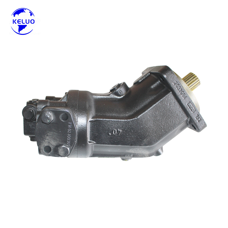
Engineers frequently compare different axial piston motor designs during system development. Geometric efficiency varies significantly between configurations. We see notable differences in volumetric and mechanical efficiency at maximum displacement settings. Swashplate units typically max out at a 20-degree to 21-degree tilt angle. A bent-axis unit usually reaches a 40-degree maximum displacement angle safely. This larger angle creates a much longer piston stroke internally. The longer stroke converts hydraulic pressure into mechanical torque more efficiently. You maximize power transmission from the fluid to the output shaft.
Torque output is absolutely critical for heavy mobile machinery. Track drives must move a heavy, stationary machine out of deep mud constantly. This requires immense starting torque right from zero RPM. Bent-axis designs achieve superior starting torque efficiency naturally. The steep internal angle directly amplifies the twisting force applied to the drive shaft. This geometric advantage prevents the machine from stalling in tough conditions. It gives operators the confidence to tackle severe inclines and unstable terrain. High starting torque also reduces strain on the main hydraulic pump.
You must evaluate speed versus pressure trade-offs carefully. Swashplate motors often offer highly compact variable-displacement packaging. They fit easily into tight machine spaces where room is limited. However, bent-axis designs win in sustained high-pressure durability over long periods. They safely handle continuous pressures up to 400 bar or more. Swashplate designs often suffer accelerated wear under similar continuous loads. We recommend bent-axis architecture when durability takes priority over compact packaging. Industrial applications clearly favor designs prioritizing longevity. You must balance physical constraints against expected operational lifespans.
Table 1: Architectural Comparison of Axial Piston Designs
Feature | Bent-Axis Design | Swashplate Design |
|---|---|---|
Maximum Displacement Angle | Up to 40 degrees | Typically 20 to 21 degrees |
Starting Torque Efficiency | Exceptionally High | Moderate to High |
Piston Lateral Forces | Virtually Eliminated | Present (Requires Slipper Pads) |
High-Pressure Durability | Excellent (400+ bar continuous) | Good (Often limited under continuous peak loads) |
Proper hydraulic motor selection requires careful evaluation of operational metrics. You must map specific torque requirements to your machine tonnage accurately. Different machine functions demand entirely different torque profiles. Swing drives need high acceleration torque to rotate the heavy upper structure smoothly. Travel drives require sustained low-speed torque for traversing rough terrain for miles. Engineers must analyze these profiles to avoid undersizing the drive unit. An undersized unit overheats quickly and destroys internal seals.
Pressure ratings demand strict attention during the engineering phase. You must evaluate continuous operating pressure capabilities thoroughly. Also, you must analyze intermittent peak limits during temporary stall conditions. A final drive might hit peak pressure briefly when a track hits a large immovable rock. The unit must survive these intermittent spikes without blowing internal seals. You should always reference ISO standards for fluid power components. These established frameworks provide reliable testing benchmarks for pressure tolerances. Trusting certified benchmark data prevents costly field failures. It ensures your machine meets regional safety and performance regulations.
Installation envelopes dictate physical compatibility fundamentally. You must assess the physical footprint carefully before finalizing designs. Track frames offer very tight spaces for undercarriage components. Upper-structure swing compartments are often crowded with numerous valves and hoses. You must ensure port configurations align correctly with existing plumbing. Incorrect port orientations complicate hose routing and increase failure risks due to hose fatigue. Tight bends in hydraulic lines restrict flow and generate excess heat. Always measure the available clearance twice to ensure a perfect fit.
Field success depends heavily on proper installation and ongoing maintenance. Contamination ruins hydraulic components faster than any other single factor. You must establish stringent ISO cleanliness codes from day one. Particulate matter scores the highly polished rotary group quickly. Clean fluid prevents catastrophic internal scoring and maintains high volumetric efficiency over time. You should observe the following best practices:
Maintain a minimum ISO 4406 cleanliness level of 18/16/13 at all times.
Install high-efficiency return line filters to capture microscopic debris.
Implement routine oil sampling to identify wear metals early.
Thermal management is incredibly important for system longevity. High-pressure operations generate substantial heat rapidly during normal work cycles. Heat thins hydraulic fluid and degrades its core lubricity. You must understand the heat generation profiles of your chosen components. High-ambient-temperature environments compound this problem significantly on summer job sites. You must ensure adequate cooling circuits exist within the system design. Proper coolers maintain stable fluid viscosity during long operational shifts. They protect delicate internal bearing surfaces from metal-to-metal contact.
Case drain line constraints require strict attention during machine assembly. Excessive case pressure causes immediate mechanical problems internally. It blows out shaft seals and causes dangerous external fluid leaks. You must route case drain lines directly to the main hydraulic reservoir. These lines must remain unrestricted and appropriately sized for maximum flow. Avoid common mistakes like teeing multiple case drains together improperly. This creates artificial backpressure and ruins seals on the most sensitive excavator hydraulic motor in the entire circuit. Proper plumbing guarantees case pressure remains well below manufacturer limits.
Industry benchmarks guide confident engineering decisions globally. The Rexroth A2FM motor serves as a proven standard in fluid power. It excels in fixed-displacement bent-axis applications across many industries. It features an exceptional power-to-weight ratio. Standardized mounting flanges simplify the integration process for engineers. Many manufacturers design their machinery specifically around these standardized dimensions. This standardization allows for easier sourcing and replacement during machine overhauls. It reduces the engineering hours required to adapt new components into legacy machines.
Engineers frequently evaluate OEM versus high-tier aftermarket units. You must assess replacement options systematically to ensure reliability. Always validate the internal metallurgy of aftermarket components thoroughly. Ensure they use high-grade steel for the cylinder block and pistons. Request detailed documentation on their testing protocols before purchasing. Reliable suppliers test units under full load before shipping them to customers. Strong warranty backing provides essential peace of mind when moving away from OEM-branded units. Quality aftermarket units often deliver identical performance if manufactured to strict tolerances.
You should follow a final selection checklist closely. This step-by-step technical audit ensures complete system alignment.
Verify maximum system pump flow matches the required unit displacement perfectly.
Calculate the intended actuator speed using accurate displacement and flow figures.
Check maximum allowable shaft speeds against actual application requirements.
Confirm mounting flange dimensions match the gearbox input physically.
Review hydraulic fluid compatibility and observe minimum viscosity limits.
Ensure cross-port relief valves are correctly sized for expected pressure spikes.
Validate case drain port locations for optimal routing back to the tank.
This methodical approach prevents costly integration errors on the assembly line. It guarantees the final product operates safely and efficiently.
Matching a robust unit to an excavator requires careful engineering. It relies entirely on aligning its high-torque capabilities with physical machine constraints. You must evaluate pressure limits and exact duty cycles accurately. These robust units handle extreme starting loads effortlessly in the field. Their geometric design naturally resists internal wear under heavy shock. Proper integration ensures years of reliable service in harsh construction environments. You avoid premature component failures through diligent system planning.
Take immediate action to secure machine reliability. Consult your specific machine hydraulic schematics today. Identify maximum flow rates and pressure relief settings clearly. Contact an application engineer with your exact performance parameters. They will help verify precise sizing requirements for your next project. Do not guess when replacing critical powertrain components. Rely on hard data and proven engineering principles to maximize your machinery uptime.
A: Radial piston motors deliver immense low-speed torque but suffer from lower maximum speed limits and bulky physical footprints. Bent-axis designs offer a superior speed-to-torque ratio. They fit seamlessly into the compact planetary gearboxes used in final drives while still delivering enough starting torque to move heavy machinery.
A: Yes, many bent-axis designs allow bi-directional operation. However, specific structural differences exist between dedicated pump and motor configurations. Pumps often feature different porting layouts and specialized valve plates to optimize fluid suction. You must verify manufacturer specifications before using a motor as a pump.
A: Cavitation is a major culprit in swing drives. Rapid deceleration creates fluid voids if anti-cavitation valves fail. Cross-port relief valve malfunctions also cause dangerous pressure spikes. Furthermore, severe fluid contamination quickly scores the internal rotary group, leading to rapid volumetric efficiency loss and catastrophic failure.
A: The 40-degree angle creates a longer piston stroke compared to swashplate designs. This extended stroke increases the displacement volume relative to the motor's physical size. The steep angle also applies force to the drive shaft at a highly effective mechanical advantage, maximizing starting torque and overall efficiency.


